NMR81 Radar Tank Gauge
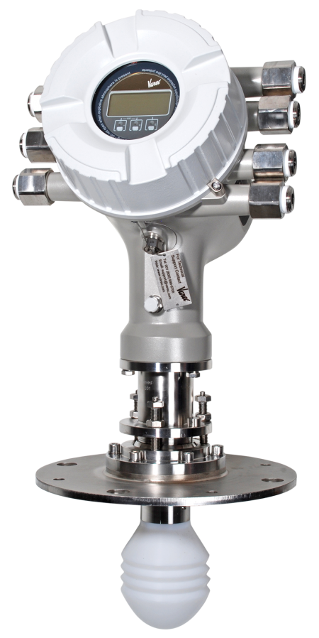
The NMR81 Radar Tank Gauge (RTG), with an accuracy rate of ±0.5 mm, is an intelligent level radar tank gauge designed for high accuracy liquid level measurement in storage and process applications.
- Overview
- Specifications
- Options
- Resources
- Related Products
Accuracy Approved for Custody Transfer

NMT81 RTG, with an accuracy level of ±0.5mm (0.02″), uses the drip-off lens antenna and has an 80 GHz transmitting frequency for custody transfer applications. The NMR81 fulfills the exacting demands of tank inventory management, inventory control, custody transfer, loss control, total cost saving, and safe operation.
Touch Screen Operations
Easy onsite operation using built-in touch control display without having to open the enclosure. It also has a user friendly operating menu.
Worldwide Approvals
Each radar gauge is approved for use in explosion hazardous areas to FM, IEC Ex, EAC and ATEX standards. It is also SIL 2 and SIL 3 certified.
Key Features
- SIL2 and SIL3 certified (Min, Max, Continuous level)
- Up to 6 SIL relay outputs
- Measures liquid level to an accuracy of ±0.5 mm (0.02 in)
- Wetted parts are completely separated from the electronic circuit
- Wide range of output signals including V1, MODBUS RS-485, HART protocol
- Tank top mounting as small as 2″/DN50 flange
- Interfaces to FuelsManager via the 8810 and 8130 Remote Terminal Unit or 8300 series TankGate
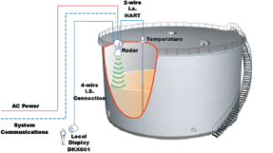
- Integration of HART instrumentation for temperature, water level, pressure, and overfill prevention sensor
- Suitable for atmospheric and high pressure applications up to 25 bar/2.5 MPa (362 psi)
- Robust IP66/68, NEMA Type 4x/6P enclosure
- Direct connection of spot or average temperature sensor
- Simplified installation and trouble-free operations due to easy connection to major DCS systems via open protocols
- Approved for use in explosion-hazardous areas
- User-friendly operating menu (multi-lingual)
- Weights & Measure-approved for use in custody transfer applications
- Unique drip-off antenna design eliminates measurement error due to condensation build-up
- Tank side monitoring and operation can be performed by the remote display and operating module DKX001
Weight
- Housing with electronics: approx. 12 kg (26 lbs)
- Sensor and processor connections: 6 to 36 kg (13 to 80 lb); dependent on the device version
Enclosure
- Housing: Aluminum
- Antenna and Process Connection:
• 316L: Shaft and flange
• PTFE: Antenna lens
• FKM/HNBR/FFKM: Seal - Rated IP66/68, NEMA Type 4x/6P enclosure
Temperature
Ambient:
- Device: -40 to +60°C (-40 to +140°F)
- Display Module: -20 to +70°C (-4 to +158°F)
Process:
-40 to +200°C (-40 to +392°F)
Primary Output
- MODBUS RS485
- V1
- 4-20mA HART Ex d/XP, RTD input
- 4-20mA HART Ex i/IS, RTD input
Range
Calibration Range:
30 m (98 ft)
Maximum Range:
Depending upon configuration choices – 70 m (230 ft)
For calibration to regulatory standards – 30 m (98 ft)
Approvals
FM, IEC Ex, ATEX and EAC
See specifications document for more information.
Approvals & Certifications
FM, IEC Ex, ATEX and EAC approvals
SIL2 and SIL 3 certifications
Power Supply
High voltage type: 85 to 264 VAC, 50/ 60
Hz, 28.8 VA
Low voltage type: In preparation
Communication
Primary Output
- Modbus RS485
- V1
- 4-20mA HART Ex d/XP, RTD input
- 4-20mA HART Ex i/IS, RTD input
Secondary I/O Analogue
- 1 x “Ex d/XP 4-20mA HART + RTD input”
- 2 x “Ex d/XP 4-20mA HART + RTD input”
- 1 x “Ex i/IS 4-20mA HART+ RTD input”
- 2 x “Ex i/IS 4-20mA HART+ RTD input”
- 1 x “Ex i/IS 4-20mA HART + RTD input”
- 1 x “Ex d/XP 4-20mA HART + RTD input”
- None
Secondary I/O Exd
- 1 x “2x relay + 2x discrete I/O”
- 2 x “2x relay + 2x discrete I/O”
- 3 x “2x relay + 2x discrete I/O”
- 1x “MODBUS RS485”
- 1x “MODBUS RS485”, 1 x “2x relay + 2x discrete I/O”
- 1x “MODBUS RS485”, 2 x “2x relay + 2x discrete I/O”
- None
The HART Ex ia/IS active input is available by default. It needs not to be chosen explicitly when ordering a device.
Antenna
Lens antenna – 50mm/2″, 80mm/3″, 100mm/4″
Flange Type
- NPS ASME B16.5, 150 lb, 2″ to 10″
- NPS ASME B16.5, 300 lb, 2″ to 6″
- PN10/16, DN50 to DN250
- PN25/PN40, DN50 to DN150
- UNI flange DN150/6″/150, max PN1/Cl.14.5/1K, suitable for DN150 PN10/16, NPS 6″ Cl.150, 10K 150
- UNI flange DN200/8″/200, max PN1/Cl.14.5/1K, suitable for DN200 PN10/16, NPS 8″ Cl.150, 10K 200
- UNI flange DN250/10″/250, max PN1/Cl.14.5/1K, suitable for DN250 PN10/16, NPS 10″ Cl.150, 10K 250
Programming
- Local display; operation via the local display is possible without opening the device
- Configuration software (e.g. DeviceCare); connected via:
– HART
– Service port (CDI) with optional Commubox FXA291
Contact Varec for more information or see technical specifications.
Datasheet
White Paper
Application Checklists
Brochure
Technical Specifications
Manuals